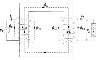
1. The Ideal Transformer (zero winding resistance, no leakage flux, linear B-H curve with an infinite permeability, no core losses) :-
A power transformer normally consists of a pair of windings, primary and secondary, linked by a magnetic circuit or core. When an alternating voltage is applied to one of these windings, generally by definition the primary, a current will flow which sets up an alternating m.m.f. and hence an alternating flux in the core. This alternating flux in linking both windings induces an e.m.f. in each of them. In the primary winding this is the 'back-e.m.f.' and, if the transformer were perfect, it would oppose the primary applied voltage to the extent that no current would flow. In reality, the current which flows is the transformer magnetising current. In the secondary winding the induced e.m.f.is the secondary open-circuit voltage. If a load is connected to the secondary winding which permits the flow of secondary current, then this current creates a demagnetising m.m.f. thus destroying the balance between primary applied voltage and back-e.m.f. To restore the balance an increased primary current must be drawn from the supply to provide an exactly equivalent m.m.f. so that equilibrium is once more established when this additional primary current creates ampere-turns balance with those of the secondary. Since there is no difference between the voltage induced in a single turn whether it is part of either the primary or the secondary winding, then the total voltage induced in each of the windings by the common flux must be proportional to the number of turns. Thus the well-known relationship is established that :
E1/E2 = N1/N2
and, in view of the need for ampere-turns balance:
I1N1 = I2N2
where E, I and N are the induced voltages, the currents and number of turns respectively in the windings identified by the appropriate subscripts.
 |
| Fig. 1 Ideal transformer |
2. Transformer voltage and current relationship
Where :
V1 = the voltage across the primary winding,
V2 = the voltage across the secondary winding,
N1 = the number of turns in the primary winding,
N2 = the number of turns in the secondary winding,
I1 = the primary current,
I2 = the secondary current.
E1 = Primary induced e.m.f
E2 = Secondary induced e.m.f
E1 = Primary induced e.m.f
E2 = Secondary induced e.m.f
3. Equivalent Circuit of transformer
3.1 Practical transformer
Analysis presented for the ideal transformer is merely to explain the fundamentals of transformer action; such a transformer never exists and the equivalent circuit of a real transformer shown in figure. 2
 |
| Fig. 2 Practical transformer |
Whenever a magnetic material undergoes a cyclic magnetization, two types of losses, eddy and hysteresis losses, occur in it. These losses are always present in transformers as the flux in their ferromagnetic core is of alternating nature.
The hysteresis loss and eddy loss are minimized by use of a better grade of core material and thinner laminations, respectively. The total no-load current Io, consists of magnetizing component Im responsible for producing the mutual flux φm and core loss component Icaccounting for active power drawn from the source to supply eddy and hysteresis losses. The core loss component is in phase with the induced voltage and leads the magnetizing component by 90°. With the secondary winding open-circuited, the transformer behaves as a highly inductive circuit due to magnetic core, and hence the no-load current lags the applied voltage by an angle slightly less than (Im is usually much greater than Ic ). In the equivalent circuit shown in figure 3, the magnetizing component is represented by the inductive reactance Xm whereas the loss component is accounted by the resistance RC.
Let R1and R2 be the resistances of windings 1 and 2, respectively. In a practical transformer, some part of the flux linking primary winding does not link the secondary. This flux component is proportional to the primary current and is responsible for a voltage drop which is accounted by an inductive reactance XL1 (leakage reactance) put in series with the primary winding of the ideal transformer. Similarly, the leakage reactance XL2 is added in series with the secondary winding to account for the voltage drop due to flux linking only the secondary winding. One can omit the ideal transformer from the equivalent circuit, if all the quantities are either referred to the primary or secondary side of the transformer. For example, in equivalent circuit of figure 3 (b), all quantities are referred to the primary side, where
This equivalent circuit is a passive lumped-T representation, valid generally for sinusoidal steady-state analysis at power frequencies. For higher frequencies, capacitive effects must be considered, For any transient analysis, all the reactances in the equivalent circuit should be replaced by the corresponding equivalent inductances.
 |
| (a) |
Fig 3 Equivalent circuit
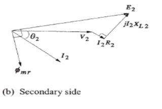
4. Vector Diagram
V1 = E1 + (R1 + jXL1) I1
V2 = E2 - (R2 + jXL2 ) I2
The core loss is given as :
Pc = IcE1
or
The mutual reactance Xm is
Fig. 4 Vector diagram of transformer
5. Simplified equivalent circuit
Where :
I2' = Load component of total primary current.
I2' = Load component of total primary current.


0 comments:
Post a Comment